Last updated: August 14, 2026
Search for an RV solar panel wiring diagram and you get a wall of colored lines that all look slightly different from each other. They are mostly the same system. Once you can name the five things every diagram contains and understand why they sit in that order, you can read any of them, including the one in the manual that came with your controller.
This explainer walks the chain from the roof to the battery, covers the series versus parallel decision that changes the diagram most, and shows where the protection devices belong. It stays on the 12 volt side throughout, which is exactly why solar is one of the more approachable RV upgrades. The moment household outlets enter the picture, the rules change, and that boundary is spelled out near the end.
This article contains affiliate links. If you buy through them, we may earn a commission at no extra cost to you. Learn more.
Quick Answer
How is an RV solar system wired?
- Panels connect to each other, pass through a roof entry gland, reach a charge controller, and the controller connects to the battery bank through a fuse or breaker.
- Panels never connect straight to a battery. The controller exists to regulate voltage and stop the bank being overcharged.
- Series raises voltage and suits MPPT controllers and long runs. Parallel keeps voltage low and copes better with partial shade.
The Chain from Roof to Battery
Every RV solar diagram, however it is drawn, contains these stages in this order. Anything extra is monitoring or convenience.
| Stage | What it is | Why it is in the diagram |
|---|---|---|
| 1. Solar panels | One or more panels on the roof, wired in series, parallel, or a mix | The source. Their arrangement sets the voltage and current arriving downstream |
| 2. Array connectors | Weatherproof connectors, branch connectors, or a small combiner box | Joins panels into strings and keeps the joints sealed against weather |
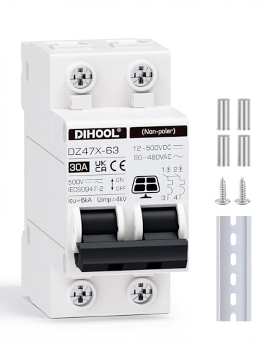
| 3. PV disconnect | A breaker or switch on the panel side, optional but useful | Lets you isolate the array for service without climbing on the roof |
| 4. Roof entry | A sealed cable entry gland | The only clean way through the membrane, with strain relief built in |
| 5. Charge controller | MPPT or PWM, mounted near the battery | Regulates panel output into a charge profile the battery can accept |
| 6. Battery fuse or breaker | On the controller-to-battery positive, close to the battery | Protects the cable, which is the whole point of overcurrent protection |
| 7. Battery bank | Lead acid, AGM, or lithium house batteries | The storage. Everything else in the coach draws from here |
| 8. Loads | 12 volt distribution panel, and an inverter if fitted | Where the stored energy actually gets used |
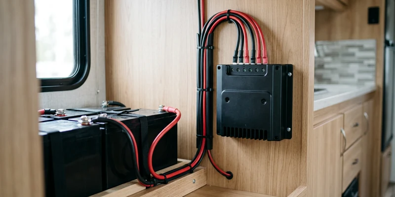
Two things are worth noticing. The controller sits near the battery, not near the panels, because the short heavy cable belongs on the battery side. And the fuse sits near the battery too, because a fuse only protects the cable downstream of itself.
Series, Parallel, or a Mix
This is the decision that makes two diagrams look different, and it is a genuine tradeoff rather than a right answer. Series wiring connects positive to negative down a chain so voltages add while current stays the same. Parallel wiring joins all positives together and all negatives together so current adds while voltage stays the same.
| Arrangement | What it does | Best suited to |
|---|---|---|
| Series | Voltage adds, current stays the same | MPPT controllers, longer cable runs, thinner wire, unshaded roofs |
| Parallel | Current adds, voltage stays the same | PWM controllers, shaded roofs, systems where one panel may be blocked |
| Series-parallel | Strings in series, then those strings in parallel | Larger arrays that need both a workable voltage and a manageable current |
Why shade pushes people toward parallel
In a series string, current has to pass through every panel, so a heavily shaded panel drags the whole string down. In parallel, each panel contributes independently and a shaded one simply contributes less. RV roofs are crowded with vents, antennas, and air conditioner shrouds that throw moving shadows all day, which is why many owners with small arrays stay parallel even though series is electrically tidier.
Why series suits MPPT
An MPPT controller converts surplus panel voltage into extra charging current, so it actively benefits from a higher input voltage. Series also lets you use thinner cable for the roof run, since the same power moves at lower current. The limit is the controller’s maximum PV input voltage, and it is a hard limit: panel open circuit voltage rises as temperature falls, so a string that is comfortable on a warm afternoon can exceed the rating on a freezing morning. Leave real margin rather than designing to the number on the sticker.
Why Panels Never Connect Straight to a Battery
It is the most common beginner question, and the answer is short. A 12 volt nominal panel does not produce a friendly 12 volts. Typical panels of that class sit somewhere in the high teens to low twenties for open circuit voltage, well above what a 12 volt battery wants to see, and they deliver whatever the sun allows with no regard for whether the battery is full.
The charge controller solves both problems. It holds output to the correct charging voltage for your chemistry, tapers current as the bank fills, and blocks reverse current at night so the battery does not discharge back through the panels. Skipping it does not save money, it costs a battery bank.
Where the Fuses and Breakers Go
Protection appears in up to three places in a full diagram, and only one of them is non-negotiable.
- Controller to battery, mandatory. A fuse or DC breaker on the positive, as close to the battery as practical, sized to the controller’s rating and the cable. Every feed from a battery bank needs this.
- Panel side disconnect, strongly recommended. A breaker or switch between array and controller lets you isolate the panels for service. It is also the polite way to shut down a system without covering panels in the rain.
- Per-string fuses, situational. With two parallel strings, a fault in one cannot generally overload the other. Once you have three or more strings in parallel, in-line fuses on each string are standard practice, because the remaining strings can feed a fault in the failed one.
For parallel arrays, branch connectors with matching in-line fuses handle both the joining and the protection in one tidy set of parts on the roof.

On the battery side, a properly rated DC breaker doubles as your service disconnect, which is worth more than it costs in convenience alone.
Wire Gauge, Length, and Voltage Drop
Two runs in the diagram carry different demands, and treating them the same is a common error. The roof run from array to controller carries relatively low current, particularly in a series arrangement, so moderate gauge outdoor rated solar cable is usually sufficient. Around 10 AWG is a common choice for typical RV arrays, but size it from your actual current and length rather than habit.
The controller to battery run is the one that matters most. It carries the full charging current at battery voltage, and voltage drop here directly reduces charging performance and can confuse the controller’s regulation. Keep it short, size it generously, and use properly crimped terminals. This is exactly the same principle that causes false alarms on inverter installs, described in our guide to inverter beeping and shutdowns: the electronics can only respond to the voltage they actually see.
Adding an Inverter to the Diagram
Solar and inverters are frequently drawn on the same page, which confuses their relationship. Solar fills the battery, the inverter empties it, and they never connect to each other directly. Both attach to the battery bank, and the bank is the hub of the entire diagram.
That distinction also marks the safety line. Everything described so far is 12 volt DC work: normal owner territory with the standard precautions of opening the battery disconnect, pulling fuses before handling cable ends, keeping panels covered while wiring, and removing jewelry near battery posts. The inverter’s DC cabling follows the same rules. Its 120 volt output does not. Hardwiring inverter output into the coach’s AC distribution, adding a transfer switch, or altering neutral to ground bonding is work for a certified RV technician, as covered in how to wire an RV inverter. If you want to understand the split between the two voltage worlds first, start with inverter versus converter.
Common Mistakes to Avoid
- Mixing panel types in one string. Panels with different voltage and current ratings in series or parallel drag each other down. Match them.
- Designing to the sticker voltage. Cold weather raises open circuit voltage, and a string that just fits in summer can exceed the controller’s limit on a frosty morning.
- Putting the controller on the roof. It belongs near the battery, where its regulation and its heavy cable make sense.
- No fuse between controller and battery. The single most commonly omitted part of the diagram, and the least optional.
- Three or more parallel strings without string fuses. A fault in one string can be fed by the others.
- Undersized controller to battery cable. It quietly steals charging performance and no display will tell you.
- Wiring panels before the battery. Most controllers want to detect battery voltage first, so connect the battery side first and uncover the panels last.
Frequently Asked Questions
Can I wire solar panels directly to my RV battery? No. Panel voltage is higher than a 12 volt battery wants and is unregulated, so a charge controller is required to protect the bank and to stop reverse current at night.
Series or parallel for RV solar? Series suits MPPT controllers, longer runs, and open roofs. Parallel copes better with partial shade, which is common on an RV roof, and pairs with simpler PWM controllers.
What size wire do I need for RV solar? Size from your actual current and cable length. Around 10 AWG covers many typical roof runs, while the controller to battery run should be short and generously sized.
Do I need a fuse between the solar controller and the battery? Yes. It is the one piece of protection nobody should skip, and it belongs close to the battery so it protects the whole cable.
Where does the charge controller mount? Near the battery bank, inside a dry, ventilated space, keeping the controller to battery cable as short as the layout allows.
Can solar and shore power charge at the same time? Yes. The converter and the solar controller both feed the same bank and simply share the work, though each regulates independently. Our installation walkthrough covers commissioning both together.
The Bottom Line
Every RV solar diagram is the same chain: panels, connectors, roof entry, charge controller near the battery, a fuse, then the bank that feeds everything else. Series raises voltage for MPPT and long runs, parallel survives the shade that RV roofs create, and the controller to battery cable deserves the most attention because voltage drop there silently costs charging performance. Keep panels covered while wiring, connect the battery side first, and remember that solar stays on the 12 volt side while inverter output does not.