Last updated: August 14, 2026
Most people looking for an RV inverter installation diagram expect something complicated. The layout is actually simple: battery, fuse, switch, inverter, and then whatever you plug into it. What makes the job serious is not the diagram, it is the current. An inverter running a kitchen appliance can move well over a hundred amps through a short piece of cable, and cable that is too small, badly crimped, or unfused is a genuine fire risk in a vehicle that shakes down the interstate at speed.
So this walkthrough treats the DC side as real work with real precautions, and it is honest about where the job ends. Mounting the inverter, running and fusing the battery cables, and plugging appliances into the unit is owner-level work. Connecting the inverter’s 120 volt output into the coach’s AC distribution, adding a transfer switch, and anything involving neutral to ground bonding belongs to a certified RV technician, and this guide will not pretend otherwise.
This article contains affiliate links. If you buy through them, we may earn a commission at no extra cost to you. Learn more.
Quick Answer
How do you wire an inverter in an RV?
- The chain is battery positive, main fuse, disconnect switch, inverter, with a matching negative cable straight back to the battery negative or the main DC ground.
- Keep the cable run short and size it from the inverter manual, then fuse it as close to the battery positive post as practical.
- Plug-in use of the inverter’s own outlets is DIY. Hardwiring the output into the RV’s 120 volt system is a certified RV technician job.
The Wiring Diagram in Words
Every correct installation follows the same chain in the same order. Read it top to bottom and you have the diagram, whether your unit is a small 1000 watt inverter or a large inverter/charger.
| Stage | What connects | Why it is there |
|---|---|---|
| 1. Battery bank | House batteries, terminals clean and tight | The source. Bank capacity, not inverter size, sets how long you can run |
| 2. Main DC fuse | On the positive cable, as close to the battery positive as practical | Protects the cable itself. This is the single most important part of the install |
| 3. Disconnect switch | Positive cable, between fuse and inverter | Lets you kill the inverter feed for service and storage without pulling fuses |
| 4. Positive cable to inverter | Heavy gauge, short as the layout allows | Voltage drop here causes false low voltage alarms |
| 5. Negative cable | Inverter negative back to battery negative or the main DC ground point | Must match the positive in gauge. A thin ground is the classic hidden fault |
| 6. Chassis ground lug | Inverter case ground to the vehicle chassis | Safety grounding required by most manuals, separate from the DC negative |
| 7. Remote panel (optional) | Small data cable to a switch panel inside the coach | Turns the unit on and off without crawling into the bay |
| 8. AC output | Either the inverter’s own outlets, or a hardwired feed | Outlets are DIY. Hardwiring into the coach panel is technician work |
Notice what is not in the chain: nothing between the battery and the fuse except the shortest piece of cable you can manage, and no shared circuits on the DC side. The inverter gets its own feed, straight from the bank.
Before You Touch Anything: Sizing and Location
Two decisions made before the first bolt goes in determine whether the install behaves for years or alarms every evening. Get them right on paper first.
Cable gauge and run length
Current on the DC side is roughly the load in watts divided by ten to twelve at 12 volts, so a 2000 watt draw is asking for something in the region of 170 to 200 amps. Manufacturers publish a required gauge and a maximum run length for each model, and those numbers are not padding. As a general pattern, mid-size units in the 1000 watt class commonly call for cable in the 4 AWG range, while 2000 watt class units commonly call for 1/0 to 2/0, with the run kept short, often under about ten feet total. Always take the figure from your own manual, because it accounts for the exact current and the acceptable drop. Use fine-strand copper cable rated for vehicle use, not solid or aluminum, and crimp lugs properly rather than twisting and taping.
Where the inverter goes
Close to the battery, in a ventilated space, on a solid mounting surface, with the manufacturer’s clearance around the case for airflow. Avoid sealed cabinets, avoid bays that bake in afternoon sun, and keep it out of the wet bay. One rule is absolute: do not mount an inverter in a compartment that houses vented flooded lead acid batteries. Those batteries release hydrogen when charging, and inverters contain relays and contacts that spark. Sealed AGM and lithium batteries do not vent in normal use, which is one reason most modern installs pair them together.
Fusing: The Part People Skip
The fuse is not there to protect the inverter, which has its own internal protection. It is there to protect the cable, because a heavy cable shorted against the frame will glow before anything else in the system reacts. That is why it goes as close to the battery positive post as the layout allows, and why standards call for it to sit right at the source of power rather than somewhere convenient at the other end.
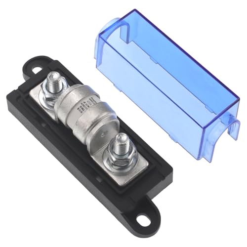
Size it above the inverter’s maximum continuous DC current and below the cable’s rating. The usual arithmetic is continuous watts divided by the lowest working battery voltage, divided again by the efficiency figure from the manual, then rounded up to the next standard fuse size. Fuse type matters as well: ANL and MRBF fuses are common on lead acid systems, while lithium banks can deliver such high short circuit current that many installers specify a Class T fuse, which is built to interrupt it safely. Check your battery manufacturer’s guidance, because several lithium makers state a preference explicitly.
A dedicated fuse block mounted at the battery, with the correct fuse for your inverter’s rating, is the piece most DIY installs are missing.
Step by Step on the 12 Volt Side
Work in this order. The sequence exists so that nothing is ever live while you are handling a cable end.
- Shut everything down. Unplug shore power, switch the generator off, turn off the inverter and the 12 volt master, and open the battery disconnect. Remove rings, watches, and metal bracelets before going near battery posts.
- Disconnect the battery negative first. Negative off first, positive second. On reassembly you reverse that, which keeps a dropped wrench from bridging positive to chassis.
- Mount the inverter. Bolt it to a solid surface, in the orientation the manual specifies, with the required air clearance. Mount it so the fan intake is not facing a wall or a storage bin.
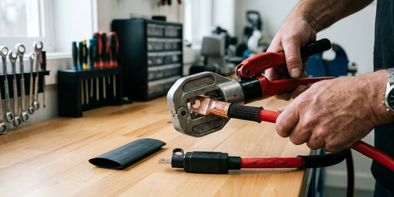
- Cut and terminate the cables. Measure the actual route, cut to length, and crimp lugs with a proper hex or hydraulic crimper. Heat shrink over each lug keeps moisture out. Never solder a high current lug as the only connection.
- Route and protect. Run positive and negative together where possible, support the cable every foot or so, and fit grommets or split loom anywhere it passes through metal. Vibration plus a sharp edge is how installs fail two seasons later.
- Fit the fuse holder and disconnect switch. Both go on the positive side, fuse nearest the battery, switch after it. Leave the fuse out and the switch open for now.
- Land the cables on the inverter. Negative to the inverter negative terminal, positive to the positive terminal, torqued to the manual’s figure. Loose terminals overheat, and overheating terminals is the most common cause of melted lugs.
- Connect the chassis ground. Run the case ground lug to a clean, paint-free chassis point with a lug and a star washer. This is a separate conductor from the DC negative, not an alternative to it.
- Reconnect the battery. Positive first, then negative. Expect a small spark as the inverter’s capacitors charge, which is normal.
- Fit the fuse and close the switch. Then power up the inverter with no load and confirm it reports normal voltage before plugging anything in.
- Test under load, and measure. Run a real appliance and compare voltage at the battery posts with voltage at the inverter terminals. A significant gap means the cable run needs attention rather than the inverter.
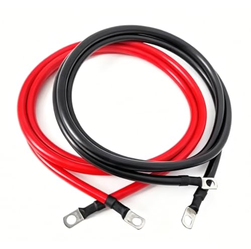
If step eleven shows a meaningful drop, or your terminals run warm, the cable set is the fix. A matched kit with correctly sized cable and pre-crimped lugs removes the two variables most likely to go wrong.
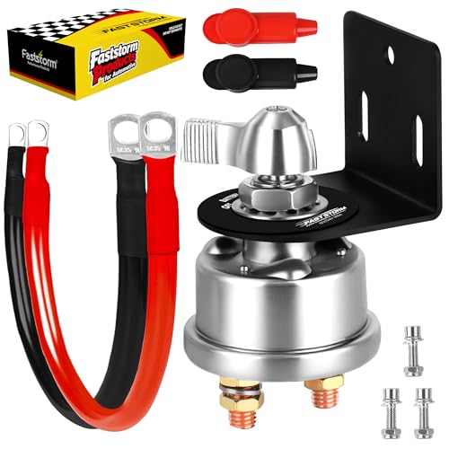
A proper disconnect switch is worth adding at the same time. It lets you isolate the inverter for storage or service without pulling a large fuse, which is exactly the kind of small convenience that keeps people from leaving the unit powered up all winter.
The 120 Volt Side: Where You Stop
There are two ways to use an installed inverter, and only one of them is a DIY job.
Plug-in use, which is fine
Every inverter has outlets on its case. Plugging appliances directly into them, or running a properly rated extension to a location you use, involves no changes to the coach wiring at all. Many owners run this way permanently and never miss the alternative.
Hardwiring, which is not
Feeding the inverter output into your RV’s outlets requires a transfer mechanism so that shore power and inverter power can never meet, correct handling of the neutral to ground bond, and a subpanel or dedicated circuits so the converter is not accidentally fed by the inverter. Get any of that wrong and you can energize a shore cord, defeat the coach’s ground fault protection, or create a loop where the converter charges the battery with power the inverter just took out of it. That is a certified RV technician’s job, and it is worth paying for. Two symptoms mean you stop using the system immediately and call one: a campground breaker that trips when you plug in, and any tingle when touching the coach body with bare feet on the ground.
Common Mistakes to Avoid
- No fuse, or a fuse at the wrong end. The fuse protects the cable and must sit at the battery, not at the inverter.
- Undersized or overlong cable. This is the number one cause of low voltage alarms on a healthy battery bank.
- A thin negative cable. Negative must match positive in gauge. Using the chassis as the return path for inverter current is not an acceptable substitute.
- Twisted and taped connections. High current joints need proper crimped lugs and correct torque, every time.
- Mounting near vented flooded batteries. Hydrogen gas and sparking relays do not belong in the same compartment.
- Hardwiring the output yourself. Transfer switching and bonding are exactly where amateur installs become dangerous.
- Skipping the load test. An install that looks right at rest can still drop half a volt under load, and you will only find that with a meter.
Frequently Asked Questions
What size cable does an RV inverter need? Take it from the manual for your model. As a pattern, 1000 watt class units commonly call for cable around 4 AWG and 2000 watt class units for 1/0 to 2/0, with the run kept short.
Where should the inverter fuse go? On the positive cable, as close to the battery positive post as the layout allows. It protects the cable, so anything upstream of it is unprotected.
Can I connect an inverter straight to the battery terminals? Only through a properly sized fuse and ideally a disconnect switch. A direct unfused connection leaves a very high current cable with no protection at all.
Do I need a transfer switch? Only if you hardwire the output into the coach’s AC circuits. If you use the inverter’s own outlets, no transfer switch is involved, and that is why plug-in use stays a DIY job.
Can I wire the inverter output into my RV outlets myself? We do not recommend it. Transfer switching, bonding, and panel work are certified RV technician territory, and mistakes there can energize a shore cord or defeat ground fault protection.
Why does my new install alarm under load? Almost always voltage drop. Measure at the battery and again at the inverter terminals under the same load, and if there is a meaningful gap, the cable or the crimps are the problem. Our guide to inverter beeping and shutdowns walks through it.
The Bottom Line
The diagram is short: battery, fuse at the battery, disconnect switch, matched positive and negative cables, chassis ground, inverter. Size the cable from your manual, keep the run as short as the layout allows, crimp properly, and verify the install with a meter under real load rather than trusting how it looks. Plug-in use is yours to do, and any hardwired 120 volt connection belongs to a certified RV technician.